
I'm tired of buying new pads and rotors due to excessive heat. Aside from the AMS brake cooling kit, I am unaware of an aftermarket solution that would work for me. So, I have decided to develop one myself.
I have the Stoptech STR-60 BBK on the front with the STR-40 kit on the rear of the car. I am using titanium shims up front and do not get boiled brake fluid. However, I have early pad degredation and rotor cracking due to excessive heat. I have been running the Binary 2" nozzles with crappy front intakes. The Binary nozzles do not fit the Stoptech kit at all, so I am loosing air pressure from the sides of the nozzles--suffice it to say the set up I have now isn't viable.
I figure there are three parts to the problem: fabrication of brake duct nozzles, ducting from the front of the car, and cold air intake. I have finished the first of the three.
The first step is to fabricat a mock-up of the nozzles out of aluminium that is easy to bend and cut.
![Image]()
![Image]()
![Image]()
![Image]()
![Image]()
The Stoptech set up has more room than the stock Brembos in the center for air flow. I wanted the nozzles to fit tight enough to conform to the shape of the hub.
![Image]()
With what seemed a reasonable first design, I fabricated the nozzles from sheet titanium that I already had. I cut the parts using a cheap benchtop wood bandsaw with a metal cutting blade.
![Image]()
I cut the holes for connection to the brake bracket with numerous smaller holes and a round file.
![Image]()
I then had to bend all the sheet metal into the right shapes, which isn't as simple as it might seem.
![Image]()
![Image]()
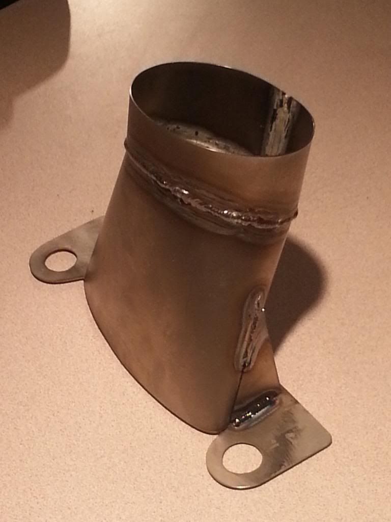
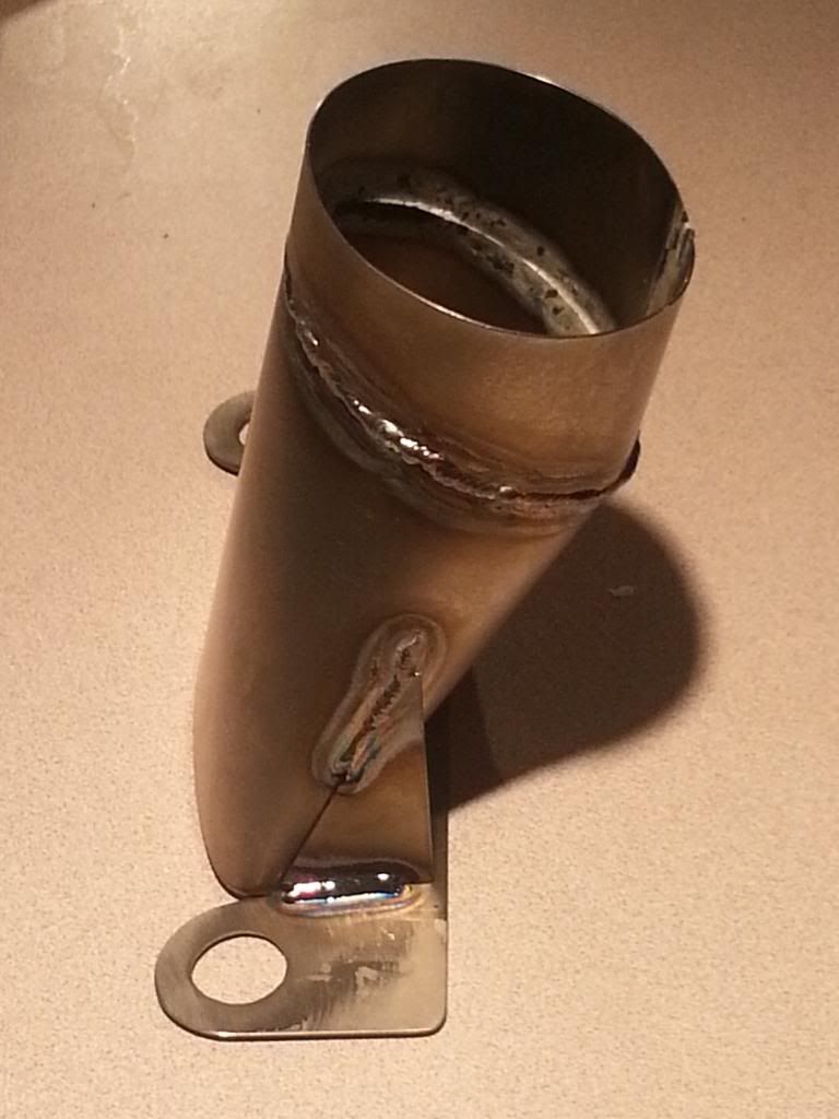
Being comfortable with a file is important here. Next, I got the nozzles welded.
![Image]()
![Image]()
I checked for fit and installed them on the car.
I have the Stoptech STR-60 BBK on the front with the STR-40 kit on the rear of the car. I am using titanium shims up front and do not get boiled brake fluid. However, I have early pad degredation and rotor cracking due to excessive heat. I have been running the Binary 2" nozzles with crappy front intakes. The Binary nozzles do not fit the Stoptech kit at all, so I am loosing air pressure from the sides of the nozzles--suffice it to say the set up I have now isn't viable.
I figure there are three parts to the problem: fabrication of brake duct nozzles, ducting from the front of the car, and cold air intake. I have finished the first of the three.
The first step is to fabricat a mock-up of the nozzles out of aluminium that is easy to bend and cut.


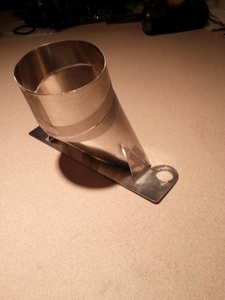
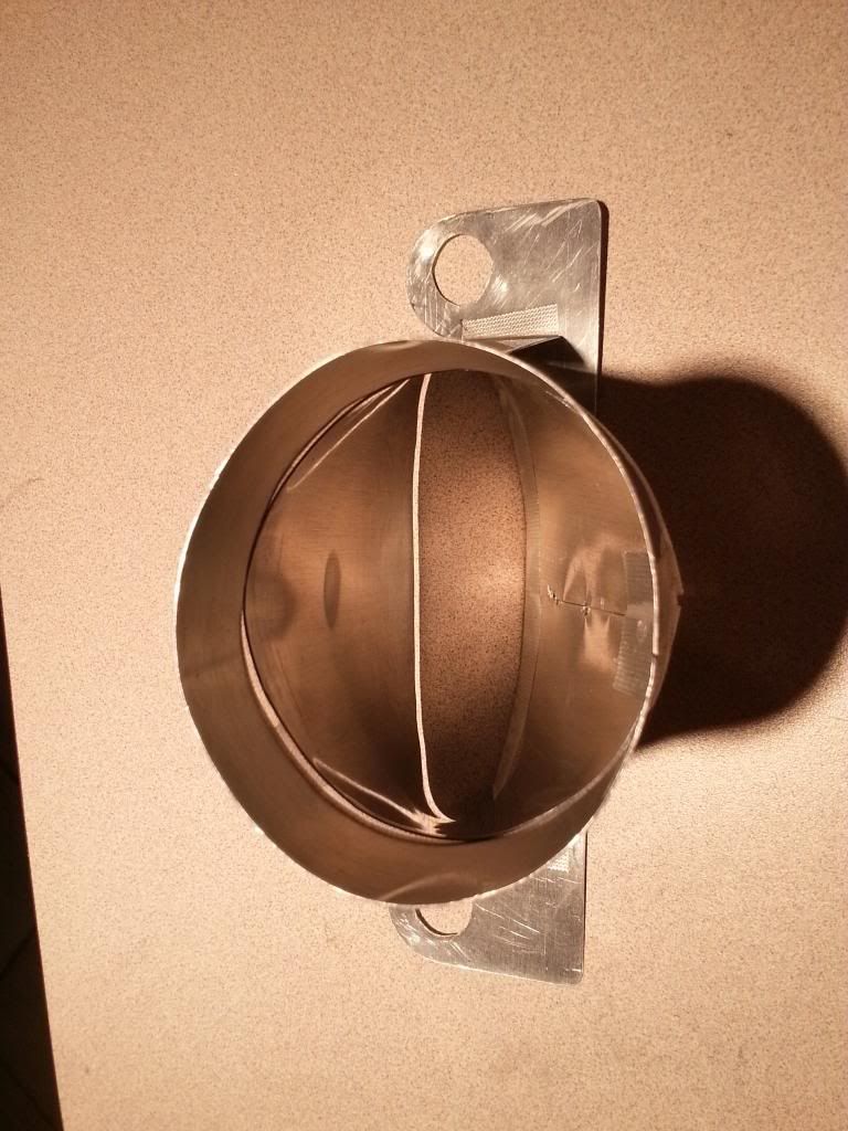
The Stoptech set up has more room than the stock Brembos in the center for air flow. I wanted the nozzles to fit tight enough to conform to the shape of the hub.

With what seemed a reasonable first design, I fabricated the nozzles from sheet titanium that I already had. I cut the parts using a cheap benchtop wood bandsaw with a metal cutting blade.
I cut the holes for connection to the brake bracket with numerous smaller holes and a round file.
I then had to bend all the sheet metal into the right shapes, which isn't as simple as it might seem.
Being comfortable with a file is important here. Next, I got the nozzles welded.
I checked for fit and installed them on the car.


")